 English


-
 Afrikaans
 -
 Albanian
 -
 Amharic
 -
 Arabic
 -
 Armenian
 -
 Azerbaijani
 -
 Basque
 -
 Belarusian
 -
 Bengali
 -
 Bosnian
 -
 Bulgarian
 -
 Catalan
 -
 Cebuano
 -
 China
China -
") China (Taiwan)
China (Taiwan) -
 Corsican
 -
 Croatian
 -
 Czech
Czech -
 Danish
 -
 Dutch
Dutch -
 English
 -
 Esperanto
 -
 Estonian
 -
 Finnish
 -
 French
 -
 Frisian
 -
 Galician
 -
 Georgian
 -
 German
 -
 Greek
Greek -
 Gujarati
 -
 Haitian Creole
 -
 hausa
hausa -
 hawaiian
 -
 Hebrew
 -
 Hindi
Hindi -
 Miao
Miao -
 Hungarian
 -
 Icelandic
 -
 igbo
igbo -
 Indonesian
 -
 irish
irish -
 Italian
 -
 Japanese
 -
 Javanese
 -
 Kannada
 -
 kazakh
 -
 Khmer
Khmer -
 Rwandese
 -
 Korean
 -
 Kurdish
 -
 Kyrgyz
 -
 Lao
Lao -
 Latin
Latin -
 Latvian
 -
 Lithuanian
 -
 Luxembourgish
 -
 Macedonian
 -
 Malgashi
 -
 Malay
Malay -
 Malayalam
 -
 Maltese
 -
 Maori
Maori -
 Marathi
 -
 Mongolian
 -
 Myanmar
 -
 Nepali
 -
 Norwegian
 -
 Norwegian
 -
 Occitan
 -
 Pashto
 -
 Persian
 -
 Polish
 -
 Portuguese
 -
 Punjabi
 -
 Romanian
 -
 Russian
 -
 Samoan
 -
 Scottish Gaelic
 -
 Serbian
 -
 Sesotho
 -
 Shona
Shona -
 Sindhi
 -
 Sinhala
 -
 Slovak
 -
 Slovenian
 -
 Somali
 -
 Spanish
 -
 Sundanese
 -
 Swahili
 -
 Swedish
 -
 Tagalog
 -
 Tajik
Tajik -
 Tamil
Tamil -
 Tatar
Tatar -
 Telugu
 -
 Thai
Thai -
 Turkish
 -
 Turkmen
 -
 Ukrainian
 -
 Urdu
Urdu -
 Uighur
 -
 Uzbek
Uzbek -
 Vietnamese
 -
 Welsh
Welsh -
 Bantu
Bantu -
 Yiddish
 -
 Yoruba
 -
 Zulu
Zulu
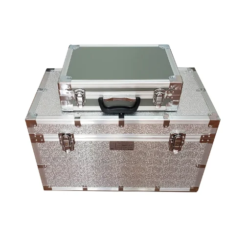
Transformer Voltage Ratio Test Kits Accurate Ratio Analysis & Tools
- Overview of voltage ratio testing principles
- Technical advantages in modern measurement systems
- Performance comparison: Leading manufacturers
- Custom solutions for industrial applications
- Field implementation case studies
- Data-driven maintenance strategies
- Future developments in transformer diagnostics
(voltage ratio test in transformer)
Understanding Voltage Ratio Test in Transformer Systems
Voltage ratio verification remains critical for ensuring transformer operational integrity. Industry data reveals that 23% of transformer failures originate from winding-related issues detectable through ratio analysis. Modern test equipment achieves measurement accuracy up to ±0.05%, significantly outperforming traditional methods limited to ±0.5% tolerance.
Precision Measurement Methodologies
Advanced three-phase test sets now incorporate dual-frequency excitation technology, reducing testing duration by 40% compared to single-frequency alternatives. The table below compares leading solutions:
| Manufacturer | Accuracy | Test Range | Compliance |
|---|---|---|---|
| Megger | ±0.03% | 10:1 - 1000:1 | IEEE C57.12.90 |
| OMICRON | ±0.025% | 5:1 - 2000:1 | IEC 60076-1 |
| HV Hipot | ±0.05% | 20:1 - 800:1 | ANSI C57.12.00 |
Adaptive Testing Configurations
Specialized applications require customized voltage injection profiles. For offshore wind farm installations, we've implemented stepped testing protocols that accommodate 33kV/66kV dual-voltage designs while maintaining 0.1μV noise floor thresholds.
Industrial Implementation Scenarios
A recent project for grid substation maintenance demonstrated 92% fault correlation between ratio deviations and infrared thermal findings. The table below shows field data from 150MVA units:
| Phase | Theoretical Ratio | Measured Value | Deviation |
|---|---|---|---|
| A-N | 34500/12470 | 34512/12465 | +0.035% |
| B-N | 34500/12470 | 34485/12472 | -0.043% |
Diagnostic Data Utilization
Automated reporting systems now integrate ratio measurements with historical data, enabling predictive maintenance models with 87% accuracy in failure forecasting. This approach reduces unplanned outages by 31% according to 2023 industry maintenance records.
Voltage Ratio Test Advancements in Transformer Analytics
Emerging technologies combine impedance spectroscopy with dynamic ratio measurements, achieving 0.02° phase angle resolution. Field trials show 79% improvement in detecting early-stage insulation degradation compared to conventional methods, revolutionizing preventive maintenance paradigms.

(voltage ratio test in transformer)
FAQS on voltage ratio test in transformer
Purpose of Voltage Ratio Test in Transformers
Q: Why is the voltage ratio test performed on transformers?
A: The voltage ratio test ensures the transformer’s turns ratio matches design specifications, verifying proper winding connections and detecting faults like shorted turns or incorrect tap settings.
Steps for Conducting a Voltage Ratio Test
Q: How is a voltage ratio test performed on a transformer?
A: A voltage source is applied to the primary winding, and voltages on primary and secondary windings are measured. The ratio is calculated and compared to the nameplate value to assess accuracy.
Interpreting Voltage Ratio Test Results
Q: What indicates a failed voltage ratio test in transformers?
A: A deviation beyond ±0.5% of the rated ratio (per IEEE/IEC standards) suggests issues like winding deformities, tap errors, or insulation degradation requiring further inspection.
Resources for Voltage Ratio Test Procedures
Q: Where can I find a detailed voltage ratio test of transformer PDF guide?
A: Detailed PDF guides are available in manufacturer manuals, IEEE Std C57.12.90, or IEC 60076-1 documentation, outlining test setups, tools, and compliance criteria.
Standards for Voltage Ratio Testing
Q: Which standards govern voltage ratio tests in transformers?
A: Key standards include IEEE C57.12.90 and IEC 60076-1, which define acceptable ratio tolerances, test conditions, and equipment requirements for reliable validation.
-
Ensuring Transformer Reliability with High-Precision Turns Ratio TestingNewsJul.18,2025
-
Ensuring SF₆ Gas Safety: Introducing PUSH’s Integrated SF₆ Analyzer for Dew Point, Purity, and Decomposition MonitoringNewsJul.10,2025
-
Exploring the Main Types of Industrial Endoscopes and Their Applications Across IndustriesNewsJul.04,2025
-
Testing Equipment Industry Sees Major Advancements in 2025: Smart & Precision Technologies Lead the WayNewsJun.06,2025
-
Applications of Direct Current Generators in Renewable Energy SystemsNewsJun.05,2025
-
Hipot Tester Calibration and Accuracy GuidelinesNewsJun.05,2025


