 English


-
 Afrikaans
 -
 Albanian
 -
 Amharic
 -
 Arabic
 -
 Armenian
 -
 Azerbaijani
 -
 Basque
 -
 Belarusian
 -
 Bengali
 -
 Bosnian
 -
 Bulgarian
 -
 Catalan
 -
 Cebuano
 -
 China
China -
 China (Taiwan)
 -
 Corsican
 -
 Croatian
 -
 Czech
Czech -
 Danish
 -
 Dutch
Dutch -
 English
 -
 Esperanto
 -
 Estonian
 -
 Finnish
 -
 French
 -
 Frisian
 -
 Galician
 -
 Georgian
 -
 German
 -
 Greek
Greek -
 Gujarati
 -
 Haitian Creole
 -
 hausa
hausa -
 hawaiian
 -
 Hebrew
 -
 Hindi
Hindi -
 Miao
Miao -
 Hungarian
 -
 Icelandic
 -
 igbo
igbo -
 Indonesian
 -
 irish
irish -
 Italian
 -
 Japanese
 -
 Javanese
 -
 Kannada
 -
 kazakh
 -
 Khmer
Khmer -
 Rwandese
 -
 Korean
 -
 Kurdish
 -
 Kyrgyz
 -
 Lao
Lao -
 Latin
Latin -
 Latvian
 -
 Lithuanian
 -
 Luxembourgish
 -
 Macedonian
 -
 Malgashi
 -
 Malay
Malay -
 Malayalam
 -
 Maltese
 -
 Maori
Maori -
 Marathi
 -
 Mongolian
 -
 Myanmar
 -
 Nepali
 -
 Norwegian
 -
 Norwegian
 -
 Occitan
 -
 Pashto
 -
 Persian
 -
 Polish
 -
 Portuguese
 -
 Punjabi
 -
 Romanian
 -
 Russian
 -
 Samoan
 -
 Scottish Gaelic
 -
 Serbian
 -
 Sesotho
 -
 Shona
Shona -
 Sindhi
 -
 Sinhala
 -
 Slovak
 -
 Slovenian
 -
 Somali
 -
 Spanish
 -
 Sundanese
 -
 Swahili
 -
 Swedish
 -
 Tagalog
 -
 Tajik
Tajik -
 Tamil
Tamil -
 Tatar
Tatar -
 Telugu
 -
 Thai
Thai -
 Turkish
 -
 Turkmen
 -
 Ukrainian
 -
 Urdu
Urdu -
 Uighur
 -
 Uzbek
Uzbek -
 Vietnamese
 -
 Welsh
Welsh -
 Bantu
Bantu -
 Yiddish
 -
 Yoruba
 -
 Zulu
Zulu
Understanding Insulation Resistance Testing Procedures for Transformers and Its Importance
Insulation Resistance Test in Transformers
Transformers are key components in electrical power systems, enabling the transfer of electrical energy between circuits through electromagnetic induction. A critical aspect of transformer maintenance and operation is ensuring that their insulation systems are functioning effectively. One of the most important tests employed to assess the condition of transformer insulation is the Insulation Resistance Test (IRT). This article discusses the rationale, methodology, and significance of performing insulation resistance tests on transformers.
Importance of Insulation Resistance Testing
The insulation material in transformers serves a vital role in preventing electrical breakdown between windings and between windings and the ground. Over time, various factors such as moisture, heat, contaminants, and electrical stress can degrade this insulation. Failing to identify and mitigate insulation issues can lead to catastrophic failures, including short circuits, fire hazards, and extensive damage to transformer infrastructure. Therefore, routine insulation resistance tests are essential in predicting the lifespan of transformers and preventing unexpected outages.
Methodology of the Insulation Resistance Test
The insulation resistance test is typically conducted using a megohmmeter, which applies a direct current (DC) voltage to the insulation system. The following steps outline the general procedure for performing an insulation resistance test
1. Preparation Before starting the test, ensure that the transformer is de-energized and properly isolated from all external connections. This is crucial to guarantee the safety of personnel and accuracy of the readings.
2. Connecting the Megohmmeter Connect the megohmmeter leads to the high voltage winding and the ground, as well as between the high voltage and low voltage windings. This setup allows for a comprehensive evaluation of the insulation resistance across different circuits.
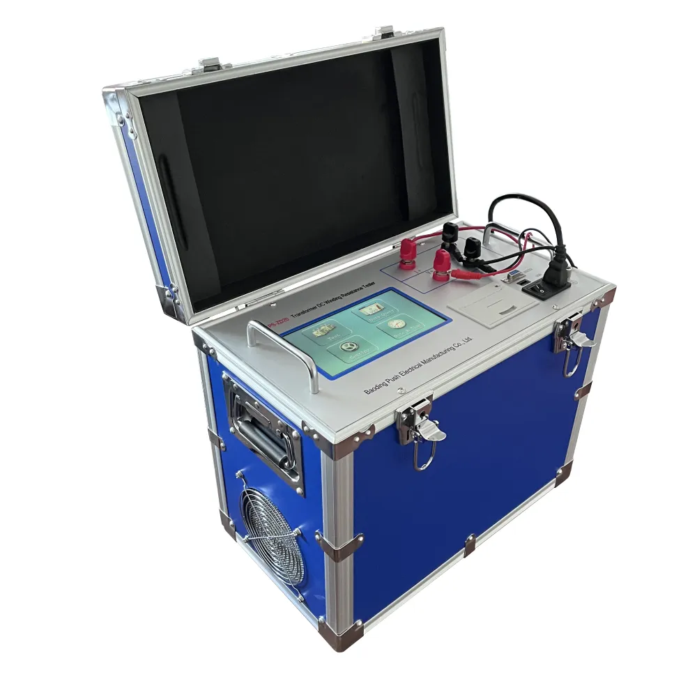
insulation resistance test in transformer

3. Applying Voltage The megohmmeter applies a specified DC voltage, often between 250V to 5,000V, depending on the transformer’s rated voltage and insulation class. The voltage level should be chosen carefully to avoid damaging the insulation.
4. Recording Readings Observe and record the resistance values obtained from the device. These readings are usually expressed in megohms (MΩ). The test duration can vary, with common practices involving a 1-minute or 10-minute test to gauge the stability of the insulation resistance.
5. Post-Test Procedure After taking readings, safely disconnect the megohmmeter. It’s essential to allow the transformer to discharge any residual voltage before re-energizing.
Analyzing Results
The results of the insulation resistance test provide insights into the health of a transformer’s insulation. Generally, higher resistance values indicate healthy insulation, while lower values may suggest deterioration or damage. Typical benchmarks suggest that readings of 1 MΩ per kV of operating voltage are acceptable; however, industry standards might vary.
If the readings are significantly low, further diagnostic tests, such as partial discharge testing or frequency response analysis, may be warranted to pinpoint the issue. Consistent long-term monitoring of insulation resistance can also help in identifying trends that signal the need for maintenance or replacement before critical failure occurs.
Conclusion
The insulation resistance test is an indispensable part of transformer maintenance, providing crucial information about insulation integrity. By routinely conducting this test, utilities and facilities can proactively address potential issues, ensuring safer and more reliable power distribution. In an era where operational continuity is paramount, the significance of insulation resistance testing in transformers cannot be overstated. The takeaway is clear regular assessments not only protect assets but also safeguard service reliability in electrical systems.
-
Testing Equipment Industry Sees Major Advancements in 2025: Smart & Precision Technologies Lead the WayNewsJun.06,2025
-
Applications of Direct Current Generators in Renewable Energy SystemsNewsJun.05,2025
-
Hipot Tester Calibration and Accuracy GuidelinesNewsJun.05,2025
-
Digital Circuit Breaker Analyzer Features and BenefitsNewsJun.05,2025
-
Benefits of Real-Time Power Quality Monitoring Devices for Industrial EfficiencyNewsJun.05,2025
-
Earth Fault Loop Testing in High-Rise Building Electrical SystemsNewsJun.05,2025


